# Design_of_1200W_LLC_DCDC
**Repository Path**: WalkingWithASnail/Design_of_1200W_LLC_DCDC
## Basic Information
- **Project Name**: Design_of_1200W_LLC_DCDC
- **Description**: No description available
- **Primary Language**: Unknown
- **License**: Not specified
- **Default Branch**: main
- **Homepage**: None
- **GVP Project**: No
## Statistics
- **Stars**: 0
- **Forks**: 0
- **Created**: 2026-07-24
- **Last Updated**: 2026-07-24
## Categories & Tags
**Categories**: Uncategorized
**Tags**: None
## README
# 1200 W · 400 V → 48 V · LLC Resonant DC-DC Converter
**Open-Source Hardware Design for Electric-Vehicle Auxiliary Power**
[](#license)
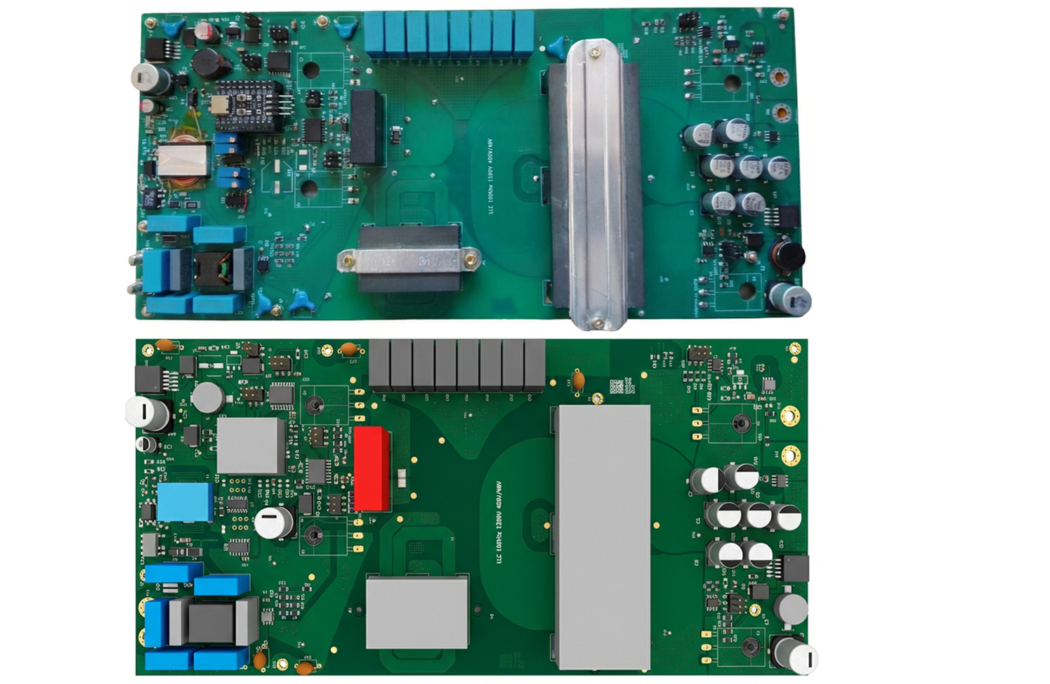
*A complete, open-source hardware project — from analytical tank design through PCB fabrication, embedded control firmware, EMC testing, and efficiency characterization — targeting the 400 V traction bus to 48 V auxiliary rail conversion found in modern electric vehicles.*
[**Interactive Project Page & Gallery**](https://boab235.github.io/pages/llc/llc.html)
---
## Table of Contents
- [Context & Motivation](#context--motivation)
- [Key Specifications](#key-specifications)
- [Repository Map](#repository-map)
- [Hardware Design](#hardware-design)
- [LLC Resonant Tank](#llc-resonant-tank)
- [Planar Magnetics](#planar-magnetics)
- [Power MOSFETs](#power-mosfets)
- [Capacitor Bank](#capacitor-bank)
- [EMI Filter (CISPR 25)](#emi-filter-cispr-25)
- [Gate Driver & HW Protection](#gate-driver--hw-protection)
- [Thermal Management](#thermal-management)
- [Schematic, PCB & BOM](#schematic-pcb--bom)
- [Embedded Firmware](#embedded-firmware)
- [Validation & Testing](#validation--testing)
- [Tools & Technologies](#tools--technologies)
- [Getting Started](#getting-started)
- [Project Page](#project-page)
- [License](#license)
---
## Context & Motivation
In battery electric vehicles (BEVs) and 48 V mild-hybrid architectures, a **high-voltage DC-DC converter** steps the 300–400 V traction battery bus down to the 48 V auxiliary rail that powers lighting, HVAC blowers, infotainment, ADAS sensors, and body-control electronics. The LLC resonant topology is the industry-preferred choice for this role because it naturally achieves **zero-voltage switching (ZVS)** across the load range, yielding high efficiency, low EMI, and compact magnetics.
This project documents the **complete physical design** of such a converter:
1. **Analytical Design** — Resonant tank optimisation, magnetic core selection, MOSFET thermal analysis, EMI filter sizing, and PCB trace calculations — all in reproducible Jupyter notebooks.
2. **Hardware Build** — KiCad schematic (V5), BOM, Gerber files, and a custom PCB with planar magnetics.
3. **Embedded Control** — 23 iterative firmware versions on an STM32F103C8T6, culminating in an adaptive PI controller with thermal derating (bare-metal C/C++, register-level).
4. **Test & Characterisation** — EMC conducted-emissions testing (CISPR 25 setup), safety tests, LLC gain & tank characterisation, and full-load efficiency measurements.
> **Note:** This is primarily a **hardware/power-electronics project**. The firmware is a supporting element written in embedded C++ on an STM32 to close the voltage-regulation loop — it is not a software product.
---
## Key Specifications
| Parameter | Value |
| ----------------------- | --------------------------------------- |
| **Topology** | Half-bridge LLC resonant (isolated) |
| **Input voltage** | 360 – 400 V DC (traction battery bus) |
| **Output voltage** | 42 – 54 V DC (nominal 48 V) |
| **Rated output power** | 1 200 W continuous |
| **Rated output current**| 25 A nominal |
| **Switching frequency** | 95 – 150 kHz (nominal ≈ 100 kHz) |
| **Transformer ratio** | n = 4 |
| **Efficiency target** | ≥ 95 % at nominal load |
| **Output voltage ripple** | < 250 mV pp |
| **Primary MOSFETs** | 2 × IPW60R037CM8 (600 V, 3.7 mΩ) |
| **Secondary MOSFETs** | 2 × FDH055N15A (150 V, 110 A) |
| **Output capacitors** | 6 × 120 µF (B40910A8127M000) |
| **Gate driver** | UCC21520Q |
| **MCU** | STM32F103C8T6 (Cortex-M3, 72 MHz) |
| **Dead time** | ≈ 100 ns (DTG register, configurable) |
| **EMI standard** | CISPR 25 conducted-emissions setup |
| **PCB revision** | V5 (latest) |
---
## Repository Map
```
Design_of_1200W_LLC_DCDC/
│
├── 01_specifications/ ← System-level specification (see companion spec document)
├── 02_architecture/ ← High-level converter architecture & block diagrams
│
├── 03_hw_design/ ── HARDWARE ──────────────────────────────────
│ ├── 01_design_justification/ ← Parametric calculations & Jupyter notebooks
│ │ ├── 01_llc_tank/ Resonant tank (Lr, Cr, Lm, Q, fn curves)
│ │ ├── 01_transformer_and_Lr_cores/ Core selection (TDK N97 planar ferrite)
│ │ ├── 02_mosfets/ MOSFET thermal & switching-loss analysis
│ │ ├── 03_resonant_and_output_capacitor/ Ripple, ESR, RMS current stress
│ │ ├── 04_measurements/ Sensor calibration (ADC ↔ voltage)
│ │ ├── 05_gate_driver/ Bootstrap & level-shift design
│ │ ├── 06_emi_filters/ CM choke, X/Y caps, damper network
│ │ ├── 07_power_supp/ Auxiliary flyback & LM2575 supplies
│ │ ├── 08_HeatSink/ Heat-sink thermal-resistance sizing
│ │ ├── 09_Hw_protection/ OVP / OCP via 74HC74 flip-flop logic
│ │ └── 10_cb_calculations/ Trace width, via current, creepage
│ ├── 02_schematic_and_bom/ ← KiCad schematics, Gerbers, BOM
│ └── 03_components/ ← Datasheet library (129 parts)
│
├── 04_sw_design/ ── EMBEDDED FIRMWARE ─────────────────────────
│ ├── 01_investigations/ STM32 & ESP32 bring-up tests
│ ├── 04_PWM_Freq_Change/ Switching-frequency modulation trials
│ ├── 05_Analog_ADC/ ADC acquisition & serial logging
│ ├── 06_Analog_ADC_TempInterp*/ Thermistor interpolation (V1 – V4)
│ ├── CONTROL/ Control firmware archive (V1 – V21)
│ ├── new_control/ Latest firmware (V22 – V23, adaptive PI)
│ └── soft_start/ Soft-start sequence analysis
│
├── 05_validations/ ── TESTING & VALIDATION ──────────────────────
│ ├── 02_emc/ CISPR 25 conducted-emissions measurement
│ ├── 03_safety/ Insulation & capacitor-discharge tests
│ ├── 04_driver_test/ Gate-driver bootstrap & dead-time check
│ ├── 05_Gain_and_LLC_Tank_charac/ LLC gain curves & Lr/Lm measurement
│ ├── 06_Fly_Back/ Auxiliary flyback converter validation
│ ├── 07_IP_controller/ Controller transient & stability tests
│ ├── 07_Prim_sec_capa/ Primary/secondary capacitor validation
│ ├── 09_LLC_Efficiency/ Full-load efficiency & loss breakdown
│ ├── 10_Buck_converter/ Auxiliary buck converter testing
│ ├── 11_HwProtection/ OCP/OVP trip-point characterisation
│ ├── 12_Divers/ Miscellaneous characterisation
│ └── soft_start/ Startup-waveform capture
│
├── 99_archive/ ← Legacy code & utility scripts
└── to_be_orgnized/ ← Draft simulations & preliminary work
```
---
## Hardware Design
Every design choice is **justified with reproducible calculations** in Jupyter notebooks, supported by LTspice simulations and component datasheets.
### LLC Resonant Tank
The resonant-tank parameters — resonant frequency $f_0$, inductance ratio $L_n = L_m / L_r$, quality factor $Q$ — were optimised to deliver the required voltage gain $M_g$ across the full 360–400 V input range while maintaining ZVS down to light load.
$$M_g = \left| \frac{L_n \cdot f_n^2}{\left[(L_n + 1) f_n^2 - 1\right] + j\left[(f_n^2 - 1) f_n Q_e L_n\right]} \right|$$
> **Notebook:** [`03_hw_design/01_design_justification/01_llc_tank/`](03_hw_design/01_design_justification/01_llc_tank/)
>
> **PDF report:** [LLC Tank Design Note](https://boab235.github.io/pages/llc/pdfs/01_LLC_48v_LLC_tank_design_note_v2.pdf)
### Planar Magnetics
Both the main transformer ($L_m ≈ 65 \text{ µH}$) and the resonant inductor ($L_r$) use **TDK N97** planar ferrite cores, chosen for low core-loss density at 100 kHz and excellent thermal conductivity. Transformer turns ratio is $n = V_{in,nom}/(2 \times V_{o,nom}) = 380/96 ≈ 4$.
> **Notebook:** [`03_hw_design/01_design_justification/01_transformer_and_Lr_cores/`](03_hw_design/01_design_justification/01_transformer_and_Lr_cores/)
>
> **PDF report:** [Magnetic Cores Design](https://boab235.github.io/pages/llc/pdfs/01_LLC_48v_LLC_Magnetic_Cores_V3.pdf)
### Power MOSFETs
| Side | Device | Rating | $R_{DS(on)}$ | Package |
|------|--------|--------|--------------|---------|
| **Primary** (half-bridge) | IPW60R037CM8XKSA1 | 600 V / 60 A | 3.7 mΩ | TO-247 |
| **Secondary** (sync. rect.) | FDH055N15A | 150 V / 110 A | low | TO-247 |
ZVS dead-time requirement: $t_{dead} \geq 16 \cdot C_{eq} \cdot f_{sw} \cdot L_m$ — set to ≈ 100 ns with margin.
> **Notebook:** [`03_hw_design/01_design_justification/02_mosfets/`](03_hw_design/01_design_justification/02_mosfets/)
### Capacitor Bank
Six **B40910A8127M000** (120 µF, 150 °C rated aluminium electrolytic) capacitors in parallel:
- **Total capacitance:** ≥ 576 µF (with 20 % worst-case derating)
- **Equivalent ESR @ 100 kHz:** 17 mΩ / 6 ≈ 2.8 mΩ (< 3.18 mΩ target)
- **Output ripple budget:** < 250 mV pp (50 % capacitive + 50 % resistive split)
> **Notebook:** [`03_hw_design/01_design_justification/03_resonant_and_output_capacitor/`](03_hw_design/01_design_justification/03_resonant_and_output_capacitor/)
>
> **PDF report:** [Output Capacitor Design](https://boab235.github.io/pages/llc/pdfs/03_LLC_48v_LLC_output_capa_v4.pdf)
### EMI Filter (CISPR 25)
Two-stage common-mode / differential-mode filter designed for automotive conducted-emissions compliance:
| Component | Value | Role |
| ----------------- | ------------------ | --------------------- |
| CM choke | PA2750NL (400 µH) | CM noise attenuation |
| Y capacitors | 4 × 2.2 nF | CM return path |
| X capacitor | 100 nF | DM filtering |
| Damper network | 27 Ω + 2.2 nF | Resonance suppression |
- **CM resonant frequency:** ≈ 170 kHz
- **DM LC cut-off:** ≈ 425 kHz
- **Leakage inductance (DM):** 1.4 µH
> **Design report:** [`03_hw_design/01_design_justification/06_emi_filters/justification.md`](03_hw_design/01_design_justification/06_emi_filters/justification.md)
### Gate Driver & HW Protection
- **Gate driver IC:** UCC21520Q with bootstrap supply for high-side drive.
- **Fast hardware protection:** 74HC74 D flip-flop latches OVP/OCP faults and disables PWM within nanoseconds — independent of firmware response time.
- **Voltage/current sensing:** Resistive dividers and ACS70331 current sensor, calibrated against 12-bit ADC ($V_{out} = 0.03081 \times ADC - 0.0976$).
> **Design files:** [`05_gate_driver/`](03_hw_design/01_design_justification/05_gate_driver/) · [`09_Hw_protection/`](03_hw_design/01_design_justification/09_Hw_protection/)
### Thermal Management
Heat-sink thermal resistance sized for worst-case junction temperature of primary TO-247 MOSFETs at full 1 200 W load, with forced-air fan controlled via TIM2 PWM on the STM32.
> **Notebook:** [`03_hw_design/01_design_justification/08_HeatSink/`](03_hw_design/01_design_justification/08_HeatSink/)
### Schematic, PCB & BOM
Designed in **KiCad**. Trace widths and via counts calculated for 25 A output current with 0.5 oz – 2 oz copper options evaluated.
| Document | Link |
| ----------------------- | ---- |
| **Schematic (PDF)** | [LLC_DCDC_V5](https://boab235.github.io/pages/llc/pdfs/LLC_DCDC_V5.pdf) |
| **Gerber & Layout** | [Gerber PDF](https://boab235.github.io/pages/llc/pdfs/LLC_DCDC_V5_Gerber_and_layout.pdf) |
| **Bill of Materials** | [BOM PDF](https://boab235.github.io/pages/llc/pdfs/LLC_DCDC_V5_BOM.pdf) |
| **Modifications log** | [Modifications PDF](https://boab235.github.io/pages/llc/pdfs/LLC_DCDC_V5_Modifications.pdf) |
> **Source files:** [`03_hw_design/02_schematic_and_bom/`](03_hw_design/02_schematic_and_bom/)
---
## Embedded Firmware
> The firmware is a **supporting element** of the hardware design — embedded C++ on an STM32, bare-metal (no HAL, no RTOS), for deterministic real-time PWM and ADC control.
```
STM32F103C8T6 @ 72 MHz
├── TIM1_CH2 (PA9) → High-side gate drive
├── TIM1_CH2N (PB14) → Low-side gate drive (dead-time DTG ≈ 100 ns)
├── ADC1 (PA0–PA7) ← Vin, Vout, Isense, Temp
├── GPIO (PB10/12) → 74HC74 flip-flop enable / reset
├── TIM2 (PA10) → Fan PWM
└── UART (CH340) → Serial telemetry @ 115 200 baud
```
**Control evolution (23 versions):**
| Phase | Versions | Strategy |
|-------|----------|----------|
| Open loop | V1 – V11 | Fixed-frequency switching |
| Closed loop PI | V12 – V16 | PI voltage regulation |
| Variable frequency | V17 – V19 | Period-based frequency modulation |
| IP controller | V20 – V21 | Alternative control topology |
| **Adaptive PI** | **V22 – V23** | **Adaptive step-delay + thermal derating** |
The latest firmware (`PI_V23_adaptive_step_delay_derating`) implements proportional-integral voltage regulation, adaptive step-delay for transient optimisation, thermal derating at elevated temperatures, and a controlled soft-start frequency ramp.
> **Latest firmware:** [`04_sw_design/new_control/PI_V23_adaptive_step_delay_derating/`](04_sw_design/new_control/PI_V23_adaptive_step_delay_derating/)
>
> **Full archive (V1 – V21):** [`04_sw_design/CONTROL/`](04_sw_design/CONTROL/)
---
## Validation & Testing
A 12-category validation campaign was carried out on the physical converter:
### System-Level Tests
| Test | Description | Report |
|------|-------------|--------|
| **EMC (CISPR 25)** | Conducted emissions via LISN | [PDF](https://boab235.github.io/pages/llc/pdfs/EMC_Conducted_Emissions_Test_V4.pdf) |
| **Efficiency** | Full-load mapping & loss breakdown | [PDF](https://boab235.github.io/pages/llc/pdfs/LLC_1200W_Efficiency_test.pdf) |
| **Safety** | Capacitor discharge & insulation | [PDF](https://boab235.github.io/pages/llc/pdfs/LLC_Safety_tests_V0.pdf) |
### Subsystem-Level Tests
| Test | Description | Location |
|------|-------------|----------|
| **LLC gain & tank** | Frequency response, Lr/Lm measurement (4 methods) | [PDF](https://boab235.github.io/pages/llc/pdfs/Gain_and_tank_characterization_V0.pdf) |
| **Gate driver** | Bootstrap transient & dead-time verification | [`05_validations/04_driver_test/`](05_validations/04_driver_test/) |
| **Controller stability** | PI transient response & stability | [`05_validations/07_IP_controller/`](05_validations/07_IP_controller/) |
| **HW protection** | OCP/OVP trip-point characterisation | [`05_validations/11_HwProtection/`](05_validations/11_HwProtection/) |
| **Soft-start** | Inrush current & startup waveforms | [`05_validations/soft_start/`](05_validations/soft_start/) |
> **All test data:** [`05_validations/`](05_validations/)
---
## Tools & Technologies
| Category | Tools |
|----------|-------|
| **Schematic & PCB** | KiCad |
| **Circuit simulation** | LTspice |
| **Design calculations** | Python 3 · Jupyter · NumPy · SciPy · Matplotlib · handcalcs |
| **Firmware** | Arduino IDE + STM32duino core (bare-metal register access) |
| **MCU** | STM32F103C8T6 (primary) · ESP32 (evaluated) |
| **USB-UART** | CH340 @ 115 200 baud |
| **Data analysis** | Pandas · Matplotlib |
| **PCB fabrication** | JLCPCB / PCBWay |
---
## Getting Started
### Browsing the Design
1. Read the [**Specification**](01_specifications/LLC_1200W_SPECIFICATION.md) to understand the top-level requirements.
2. Open the [**LLC Tank Design Notebook**](03_hw_design/01_design_justification/01_llc_tank/01_LLC_48v_LLC_tank_design_note_v2.ipynb) for resonant-converter theory and parameter selection.
3. Review the [**Schematic (PDF)**](https://boab235.github.io/pages/llc/pdfs/LLC_DCDC_V5.pdf) for the complete circuit.
4. Check the [**BOM**](https://boab235.github.io/pages/llc/pdfs/LLC_DCDC_V5_BOM.pdf) for component sourcing.
### Building the Firmware
1. Install [Arduino IDE](https://www.arduino.cc/en/software) with the **STM32duino** board package.
2. Select board: **Generic STM32F1 series → STM32F103C8**.
3. Open `04_sw_design/new_control/PI_V23_adaptive_step_delay_derating/PI_V23_adaptive_step_delay_derating.ino`.
4. Connect the STM32 Blue Pill via ST-Link or USB-to-Serial (CH340).
5. Compile and upload.
### Reproducing the Notebooks
```bash
pip install jupyter numpy scipy matplotlib handcalcs
jupyter notebook
```
Open any `.ipynb` file in `03_hw_design/01_design_justification/`.
---
## Project Page
An interactive project page with documentation, downloadable PDFs, and a photo gallery:
**[https://boab235.github.io/pages/llc/llc.html](https://boab235.github.io/pages/llc/llc.html)**
---
## License
This project is open-source under the MIT License. See the repository for details.
**[Report an Issue](https://github.com/BOAB235/Design_of_1200W_LLC_DCDC/issues) · [Project Page](https://boab235.github.io/pages/llc/llc.html) · [GitHub](https://github.com/BOAB235/Design_of_1200W_LLC_DCDC)**